About the story in short: we built a new house, and at some point we came to the question: “What should control the heating and cooling?” Should we buy something for that? Nooo, it’s too expensive and not reliable (haha)…Leave it dumb, like a plain switch? Out of the question — this was a brand-new build…it has to know everything.
Since I am an engineer, I convinced my wife that I was going to build our own house automation controller and write an application that controls it. It wouldn’t take more than a few months.
So that was three years ago XD… And in the meantime, I’ve written the software… twice.
About the building
We have four rooms (an office, a bedroom, and two children’s rooms), a living room + kitchen, a corridor, bathrooms, and a garage.
The walls have insulation (15cm PS), so floor heating itself with 30°C circulating water is enough to have comfortable ~23°C in the building during winter. In case of apocalyptic cold winters the fancoils could be used for heating too, but during normal circumstances fancoils(one per room) are for cooling, and floor heating is for heating. My friend—who was our architect—told me that I would only need one thermostat in the living room to control the heating, because I couldn’t control each room’s temperature individually due to the concrete floor’s huge thermal mass and heat conduction. According to him, having a thermostat in each room is a totally stupid idea. I told him to give his diploma back and go bake some buns (we are good friends :)). I installed a thermostat in each room, and guess what—I was right. It is easy to keep 3-4°C temperature difference between the office and bedroom which are near each other.
An last but no least, the domestic hot water (DHW) is stored in a 400l puffer tank which has a serpentine heat exchanger.
The devices
Heatpump
Midea MHA-V12W/D2RN8-B, 3 phase 12kW air/water heatpump with IBH (internal backup heater) that can be operated at 3/6/9 kW. It uses R32 gas.
Details
This device is a split heat-pump which means there is an outdoor and an indoor unit. The outdoor unit is responsible to deal with the refrigerant. The compressor compresses the gas and circulates the refrigerant between the outdoor and indoor unit’s heat exchanger. At the outdoor the heat energy is exchanged between the air and the refrigerant, and in the indoor unit, it is exchanged between the refrigerant and the water. In one sentence: the energy is exchanged between air-(refrigerant)-water. That is why this kind of device is called an air-to-water heat pump.
How heatpump works
I couldn’t resist…I need to share some theoretical details, because it is genius imo. I hope the image below helps you to understand (if you wouldn’t have known the basics already).
![]()
When we are heating, the energy moved from outside to inside (pink texts). The compressor compresses the gas to liquid. During this process the refrigerant temperature goes up (adiabatic process, no heat exchange here). Inside the indoor unit, this energy is transported to the water…it basically warms up the water. After that the liquid goes back to the outside unit and goes into the heat exchanger, where it is evaporated. During the evaporation its temperature drops (ideally with the same amount as it went up during the compression). Don’t forget that the refrigerant has already transferred some heat to the water, and this happens in the heat exchanger, so the gas is heated back by the outdoor air. After that the gas goes into the compressor, and the whole cycle starts again. This could be a bit abstract, but the point is we steal 5°C temperature difference from the air and transport this to the water. And the magic is done by the heat pump and thermodynamics.
Fancoils
Gree FPD-85BB4/A-K and Gree FPD-34BB4/A-K used controller for initialization: XE7A-17/E
Thermostats
IO expanders
ComWinTop CWT_MP308K and CWT_MP307P
USB-RS485
Controller
Raspberry Pi 2 (!)
Dashboard+metric collector computer
CSL 52233
I tried to save money on the devices I used, but it is surprising was how much Chinese equipment I ended up using… except for the Raspberry Pi and the CSL, everything is made by a Chinese company. But to save my reputation, they are not from the lowest tier, so they are good-quality products.
About the architecture
I created a schematic about how the devices are connected. It might seem to be complicated, but believe me it is not too bad.
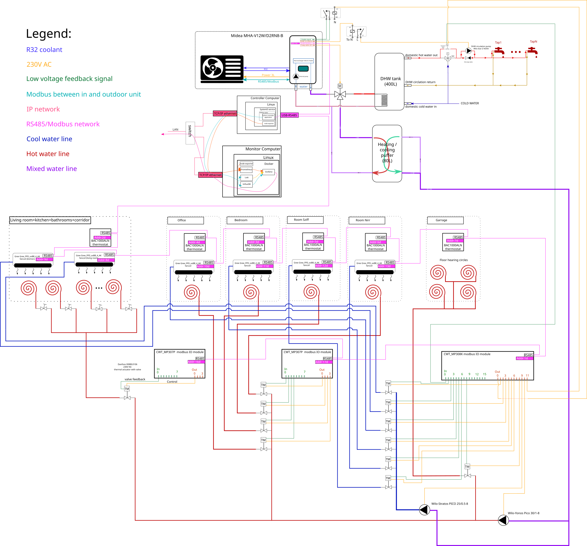
Heatpump, 3Way valve, DHW
Between the indoor and outdoor unit, there are three types of connections:
- power lines (this is a three phase heatpump)
- refrigerant lines (gas+liquid)
- communication lines (RS485+modbus)
From this point we can consider the heatpump as a blackbox unit which can make cold or warm water. When it makes warm water, we can use it either to warm the house, or heat up the water in the DHW tank.
The water from the heatpump runs into a 3 way valve which directs it either into the DHW tank(closed loop, the heating water doesn’t mix with the domestic water), or towards the heat/cool puffer tank(open loop, the water mixes with the water that circulates in the fancoils/floor heating).
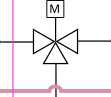
The 3 way valve is directly controlled by the heatpump, depending on which mode is activated. In my case creating DHW has a priority, so if the water temperature drops below a certain temperature in the tank, DHW mode is activated, and 3way valve directs the water to the DHW tank. During this time either the cooling, or the house heating is suspended. Fortunately heating up the whole tank (~400L) from 10-15°C to 50°C takes only around an hour(!)
DHW circulation
There is one other device which is controlled by the heatpump. This is the DHW circulation pump. It can have high power consumption during the start, so I placed a contactor to drive the pump. Contactor is basically a relay. So heatpump activates the contactor, and it activates the pump.
DHW circulation is responsible to have instantaneous hot water when you open the tap. In our house the kitchen is far away from the DHW tank, and if we didn’t have DHW circulation, we should wait minutes for the hot water and would waste a lot of water. To overcome this, there is a small pump that circulates hot water time to time in the pipes. The downside is, over time the circulated hot water becomes cold inside the pipes (regardless the pipe isolation), and the pump needs to run again. So it wastes heat energy, but compared to the volume of wasted water this is less of a pain.
Building heating/cooling
In winter, the heatpump is in heating mode. When we have enough hot water in the DHW tank, floor heating can be activated. This happens when a thermostat signals the central unit. It opens the valves assigned to the thermostat, activates the heatpump and the floor heating circulation pump. Follow the red lines in the architecture image to trace the route of the warm water. During summer (cool mode activated in the heatpump), wall thermostats are ignored, and fancoils are the source of the trigger event. If it needs cold water, central unit activates the corresponding valve, and enables the heatpump. At the end of the flow, it also enables the circulation pump of the fancoils. Blue lines are representing the cold water.
And basically that is it. Simple. Signal->Processing->Action. In the next section lets examine further how processing infrastructure comes together.
High level information about the control
The following devices are used in the control loop:
- Controller computer, or central unit: It runs the control software, and reports metrics
- Monitor computer or metric collector: Collects and stores the metrics generated by the controller computer. Also runs a webserver to provide dashboard where you can see fancy charts.
- Thermal valves: Electronically controlled valves with feedback. Control line: Yellow, 230V AC, feedback line: green, Low voltage DC
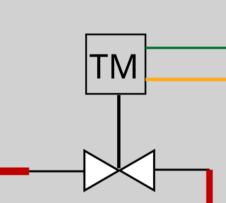
- Modbus IO expanders: A device has N output and M input. A device can be addressed and can be told to enable a particular output or read the state of an input. Pumps and control valves are controlled by the IO expanders. Since valves have feedback loop, its state can also be checked by the IO expanders.
The system can gather input from thermostats, fancoils and from the heatpump. Every device is connected to an RS485/modbus backbone. I used a cheap cat5e UTP cable, it contains 4 pair of twisted wires, and RS485 only needs one pair. The master modbus device is the usb/rs485 converter.
Coming soon: Dashboard overview, system configuration/installation, Controller software, source+explanation,
